Hey everyone – if you’re deep into the power electronics game, you’ve probably heard rectifier transformers talked about like they’re the unsung heroes of industrial operations. But let’s be real, most of the explanations I’ve seen online either go way too tech-jargon-heavy or skip the one thing that actually matters for people buying these things: what the hell is the output waveform, and why does it matter for your setup? As a rectifier transformer supplier, I work with all kinds of teams – from guys running big electroplating lines to factories churning out aluminum and copper – and I’ve lost count of how many times a client’s problem came down to not understanding that waveform. So let’s break this down like we’re chatting over a coffee, no fancy degree required. Rectifier Transformer
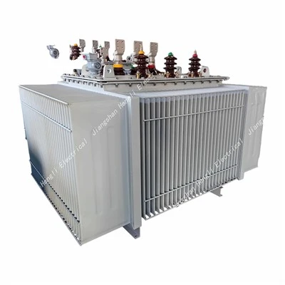
First, let’s start with the basics, no B.S. A rectifier transformer’s whole job is two things: adjust the voltage coming from the grid (it’s usually too high or too low for whatever your rectifier needs) and then feed that power to a rectifier, which turns alternating current (AC) into direct current (DC). The output waveform? That’s the shape of the electricity leaving the rectifier transformer (wait, actually, let’s get that precise – it’s more accurate to say the rectifier transformer’s output goes to the rectifier, and the rectifier’s DC output is what people usually mean when they talk about this waveform – I’ll clarify that later so we don’t mix wires up).
Let’s keep this relatable. If you’ve ever looked at a sine wave on an oscilloscope (that’s the little graph tool techs use), regular grid AC is a perfect smooth, wavy line going up and down, alternating between positive and negative. A standard single-phase rectifier’s DC output? That’s the one that looks like a sine wave but only ever stays on the positive side of the line – it’s like clipping the bottom half of the wave and flipping it up, so you get these little humps, right? That’s 120Hz ripple (for 60Hz grid) or 100Hz (for 50Hz grid) – so twice the grid frequency. But if you’re using a 6-pulse rectifier (the most common one for industrial setups), that’s where things get less bumpy. A 6-pulse rectifier’s waveform is like six of those humps stacked on top of each other, so the ripple frequency jumps to 300Hz (60Hz grid) or 300Hz too? Wait no, wait – 6 times the grid frequency, yeah: 300Hz for 50Hz grid, 360Hz for 60Hz. That’s way smoother than single-phase 120Hz.
But here’s the big point most suppliers and online guides skip: the rectifier transformer’s design directly shapes that waveform, not just the rectifier itself. Think of the rectifier as a filter – but the transformer’s winding configuration (what we call the phase shift) is what sets how clean that filter can work. For example, if you need a super low-ripple DC output for something like a battery charger or electrolytic process, you’ll want a 12-pulse or 18-pulse setup. A 12-pulse uses two rectifier transformers with a 30-degree phase shift between them, so their waveforms overlap to make even bigger, flatter humps – the ripple drops way down, usually to 600Hz or even higher. No more those annoying little dips in the DC line that can mess with your equipment.
Now, why does this matter to you? If you’re running a small electroplating line, a single-phase rectifier’s bumpy waveform might not be a huge deal… until you notice your parts have uneven plating, or your transformer is overheating because it’s working harder to smooth that ripple. If you’re in aluminum smelting, though, the waveform is non-negotiable – too much ripple and you get inconsistent current, which ruins the metal quality and wastes energy. I had a client last year who was using a cheap off-the-shelf transformer, and his 6-pulse setup had so much ripple his rectifier was failing every 8 months. Switched to our custom-designed rectifier transformer with a 12-pulse configuration, and his failure rate dropped to once every 5 years. That’s not just numbers – that’s thousands in saved downtime and repair costs.
Wait, let’s clear up a common mix-up people have: the rectifier transformer’s output is still AC, right? The transformer itself doesn’t turn AC to DC – that’s the rectifier’s job. So when people ask about the rectifier transformer’s output waveform, they’re usually referencing the AC waveform leaving the transformer, which the rectifier then converts to DC. Oh, that’s a key detail I missed earlier. So the transformer’s output is AC, but its wave shape is adjusted to work with the rectifier. For a standard 6-pulse rectifier, the transformer uses a star-delta (Yd) or delta-star (Dy) winding, which shifts the phases so when the rectifier flips it to DC, you get that low-ripple wave. If the transformer’s phase shift is off, the DC waveform gets messy – even if the rectifier is good.
I also get a lot of questions about harmonic distortion tied to the waveform. Those ripples I was talking about? They’re harmonics, basically extra frequencies that aren’t part of the original grid sine wave. Too many harmonics can cause all sorts of headaches: overheating in your motors, power factor issues, even interference with other equipment on the same grid. A well-designed rectifier transformer minimizes harmonics by shaping the output AC to cancel out most of those extra frequencies. Our team always does a harmonic analysis for every custom job we do, because cutting harmonic levels means longer equipment life and lower electricity bills for the client.
Let’s talk real-world examples to make this concrete. Last quarter, we worked with a steel mill that was upgrading their DC power supply for their rolling mill. They had a standard 6-pulse setup, but their waveform had 30% total harmonic distortion (THD) – that’s way above the industry average of 5% for industrial setups. We designed a 18-pulse rectifier transformer with a double-star winding, which cut THD down to under 3% straight away. Their power factor jumped from 0.82 to 0.95, so they stopped paying those expensive utility penalties for low power factor, and their rolling mill’s parts had 20% less scrap rate. That’s the difference between understanding the waveform and just picking any transformer off the shelf.
Another common scenario: if you’re working with sensitive electronics, like a data center’s backup power system or a medical device, you need an even cleaner DC waveform. That’s where we’ll use a 24-pulse or even higher pulse rectifier transformer, paired with active rectifiers, to get ripple levels below 1% – so smooth it’s almost a flat line, not just a series of humps. Those setups cost a bit more upfront, but they pay for themselves in reliability, no sudden shutdowns, no damaged sensitive gear.
Wait, let’s bust a myth here: a lot of people think more pulses = always better. That’s not true. If your application only needs moderate DC, like a small 100kW battery charger, a 6-pulse setup is enough – it’s cheaper, simpler, and the waveform is smooth enough for the job. There’s no need to overspend on a 12-pulse transformer if you don’t need it. The trick is matching the waveform to your specific load, not just grabbing the fanciest option.
As a rectifier transformer supplier, our whole process starts with asking the right questions: what’s your DC power requirement? What type of load are you running? What’s your local grid frequency? How strict are you on harmonic levels? Because every answer changes the waveform design. For example, a transformer for a 50Hz grid will have different pulse frequency than one for 60Hz, just like a transformer for a 1MW electrolytic cell will have a way flatter DC waveform than one for a small 10kW test bench.
I’ve seen way too many clients buy cheap transformers from overseas suppliers that cut corners on the winding design, leading to messy waveforms, high harmonics, and premature failure. That’s why we prioritize custom design over one-size-fits-all units. We test every single transformer we build on our in-house oscilloscope setup to make sure the output waveform matches the specs we agreed on – no guesswork, no surprises.
Let’s wrap this up so it’s not just a bunch of tech talk: the rectifier transformer’s output waveform (whether we’re talking about the AC it sends to the rectifier or the DC you end up using) is not just a random shape. It’s the result of how the transformer is wound, how its phases are shifted, and how it’s paired with your rectifier. The right waveform means less downtime, lower energy bills, better product quality, and longer life for your equipment.
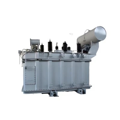
If you’re dealing with inconsistent DC power, high harmonic penalties, or equipment that’s dying too fast, don’t just guess at the solution. Reach out to our team to chat through your setup – we’ll walk you through exactly what waveform your project needs, no confusing jargon, no pressure to buy something you don’t need. We’ll even share sample waveform graphs from past jobs so you can see the difference a well-designed rectifier transformer makes. Don’t let a wonky waveform mess up your bottom line – let’s figure this out together.
Dry Type Transformer References
- Rashid, M.H. Power Electronics: Circuits, Devices, and Applications. Pearson Education, 2017.
- IEEE Standards Association. IEEE Standard for Rectifier Transformers. IEEE Std C57.12.40-2018, 2018.
- Sen, P.C. Principles of Electric Machines and Power Electronics. John Wiley & Sons, 2014.
- Electrical Construction Maintenance (EC&M). “Understanding Rectifier Transformer Waveforms and Harmonics,” EC&M Magazine, 2022.
- The Industrial Power Group. “Rectifier Transformers: Design, Application, and Waveform Performance,” IPG Technical Bulletin, 2021.
Zhejiang Jiangshan Hengli Electrical Co., Ltd.
Zhejiang Jiangshan Hengli Electrical Co., Ltd. is one of the most professional rectifier transformer manufacturers and suppliers in China, featured by quality products and low price. Please rest assured to wholesale cheap rectifier transformer in stock here and get pricelist from our factory. Customized orders are welcome.
Address: 212 Fuzhu Street Sidu Town, Jiangshan, Zhejiang, China
E-mail: henglijs@foxmail.com
WebSite: https://www.henlypower.com/
